- Receive telemetry data from APM to our 9XR screen
- Receive telemetry data on the FPV screen through MinimOSD
- No need for extra telemetry radios, no extra antennas, less interference.
- Connect to Mission planner through FTDI
- Connect to Mission planner (or Cellphone/Tablet) through Bluetooth
- Simple cellphone/tablet connection through NFC Tags.
Never power on a TX/RX module without an antenna attached to it. Not doing so you may damage them.IMPORTANT
Supply your OrangeTX/RX modules only with 3.3V. If you use 5V you will damage them.
If you are not sure you can do something, leave a professional do it for you.
Modifying things is half the fun :) so have fun and enjoy it :)
Note: I don't take any responsibility for any damage you may cause to any of your equipment. Do anything at your own risk.
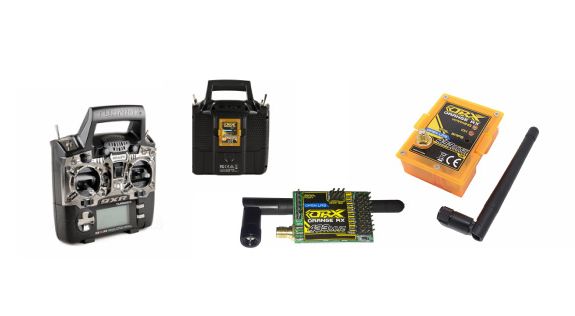
OpenLRS as the name says (Open Source Long Range System) is a great choice if you plan to fly Long Range. The lower the frequency, the greater the range. Combining this with a 1.2-1.3 Ghz or 2.4 Ghz video link would be the ideal setup. There is only one thing you need to know about this system: It is an open source one which means you have to flash firmware into the TX and RX, but no worries, there are great choices out there and great tutorials and videos about how to do it and this is also one reason i'm writing this tutorial. I have purchased the TX/RX modules from Hobbyking ( TX / RX ) and i will be describing the procedure below.
There several possibilities you can use OpenLRS systems.
1. Using TX/RX
2. Using TX/TX (using one TX as a receiver)
3. Using RX/RX (using one RX as a transmitter)
I'm using the first option, but you can use either one, all you have to do is flash the right firmware and do the mods which are easy to do.
There is also another option where you can use two orange TX modules and flash one of them as RX and this way have 1W two way radio controll system with 1W telemetry link in both ways. You can use OpenLRS as with PPM, Sbus, FrsSky, Spektrum, Mavlink, spektrum analyzer etc. It is a really versatile system, and when you consider the price, it is unbeatable.
Be advised that the mod is made for FrSky telemetry, but it is almost the same like Openlrs. The only difference is that you don't need the TX wire from the 9XR main board. You connect only the RX wire from your 9XR main board to your RF module.
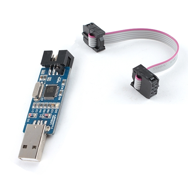
To flash the custom firmware to the radio, you will need a USBasp AVR programmer which you can buy here or you can buy on ebay. After buying the programmer, you need to install the drivers on your PC. If you buy the one from HobbyKing, remove the jumper, as it is for slow programming.
Depending on your Operating System, choose the corresponding tutorial on how to install the drivers:
After installing the drivers you will need the following files
Companion9X, which is a program that allows you to download OpenTx firmware from internet and flash it to your handset
Fig. 5 USBasp from Hobbyking
Before flashing the firmware it is a good idea to remove the TX module from your handset, even though we have protect it with the resistor in the mod. Making it a habit would be good.
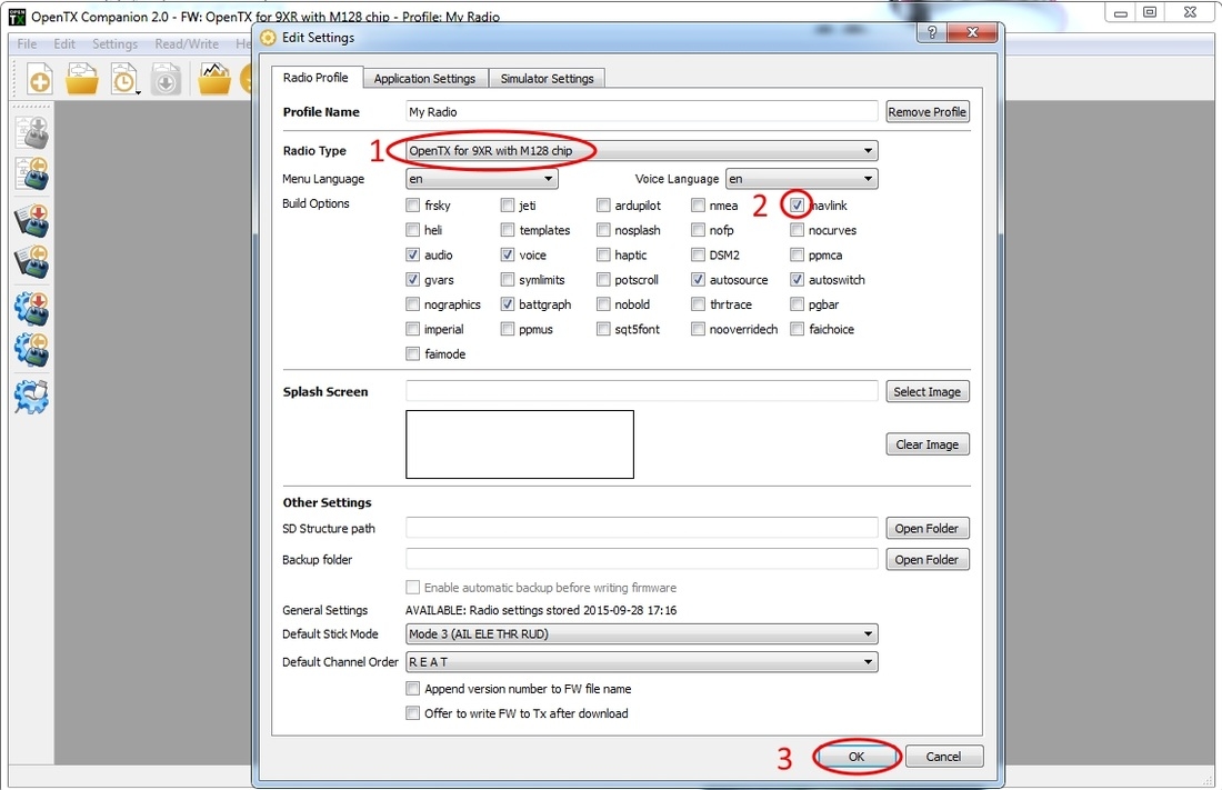
Fig. 6 Flashing OpenTX with mavlink to your handset
Turn off the 9XR remove the TX module and connect it to PC
Download and open Companion9X from the link above
Choose your handset with the right chip, select mavlink among other options you would like to have on your radio and click OK
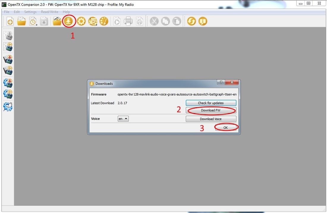
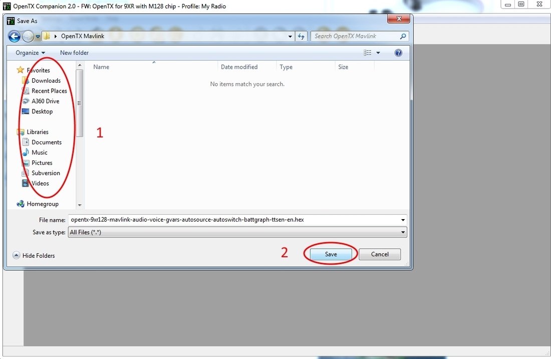
Click Arrow down button -> Download FW -> OK
Choose the path where you want to save the firmware on your PC and click Save
After the file has been saved on your computer,
Click the button on the left like in Fig. 10 to upload the firmware to your handset.
Click Browse and locate the firmware you have saved on your computer
Click Write to TX
Fig. 7
Fig.8
Fig. 9
Fig. 10
Now turn on the handset, push a button to format EEPROM, and then calibrate it
After calibrating, push and hold left button, to get into Settings Menu
Scroll down until you get to the option "Baudrate" and change it to 19200
Setup models and everything in your handset as necessary
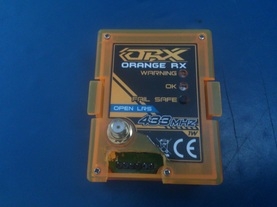
Now we are done with the radio and we will proceed with modifying the OrangeRX Open LRS Transmitter module.
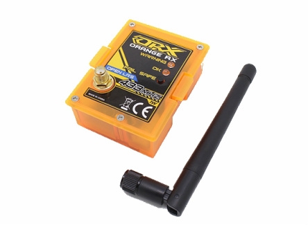
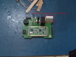
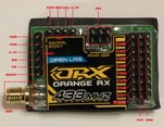
Open the OrangeRX receiver and carefully remove the antenna.
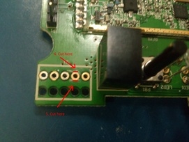
1. Desolder the pins on the the back side and carefully remove the plastic. We need to get access to the holes and isolate the GND pin in both sides of the module.
Fig. 11 Remove plastic
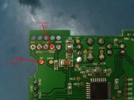
2. Cut the trace of the GND pin like in the picture. In mos cases people don't cut the trace entirely, resulting in a non working mod, so i suggest you check the connection with a mulimeter.
3. Cut the trace like in the picture to isolate resistor R2 from RF pin.
Fig. 12 Cut traces
Turn the module on the other side and cut the traces 4 and 5 like in the picture to isolate the GND pin.
Fig. 13 Cut traces on the other side
6. Solder a wire from RF pin to TX
7. Solder 1k resistor from isolated GND pin to RX
Don't pay attention to the wire marked with X in the picture. I had to solder it because i had problems with the small resistor on the left corner which was ripped off from the small rectangle which is inside the case. So be careful while closing the module
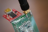
Cut the plastic open at the bottom of the TX module so you can connect the FTDI board without opening the case.
Fig. 14 Solder a 1k resistor and a wire
Fig. 15 TX with a hole to connect FTDI to the serial port
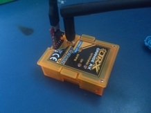
Put everything back together (don't forget to connect the antenna or you will fry your module) and we are done with the TX.
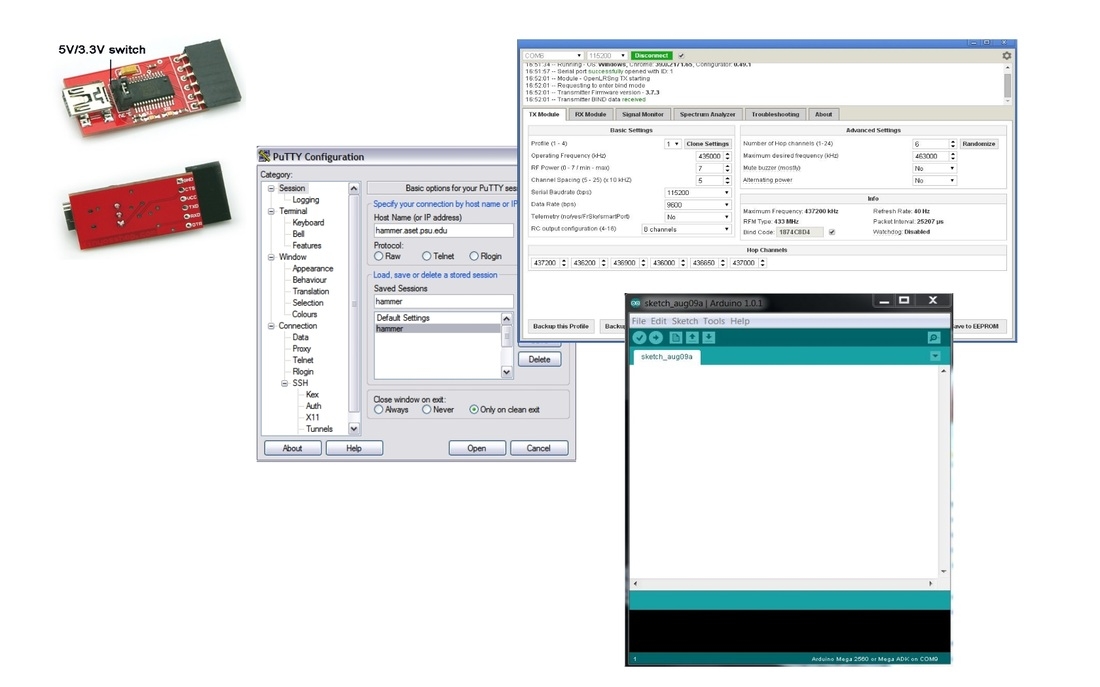
Now you need to flash the openlrsng - glitsy version to your Tranmitter/Receiver modules using Arduino IDE. I will modify the code for TX and RX so you will only have to flash the corresponding version to your TX/RX respectively. It has this configuration:
Copy libraries from one of the Glitsy folders to your Arduino libraries
Fig. 17 Coping library files to Arduino IDE libraries
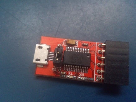
FTDI breakout board.
Fig. 18 FTDI breakout board with selectable power output 3.3V/5V
Important: TX/RX modules must be flashed with 3.3V. They are not 5V tolerant, so be careful and set the jumper on your FTDI board to 3.3V .( Not doing so may result in damaging your TX/RX modules).
Now we are ready to start flashing the firmware into the handset
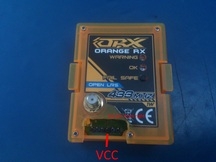
Connect the FTDI to the serial port of the TX
VCC pin is the third one from the right side
Plug the FTDI into a free USB port on your PC
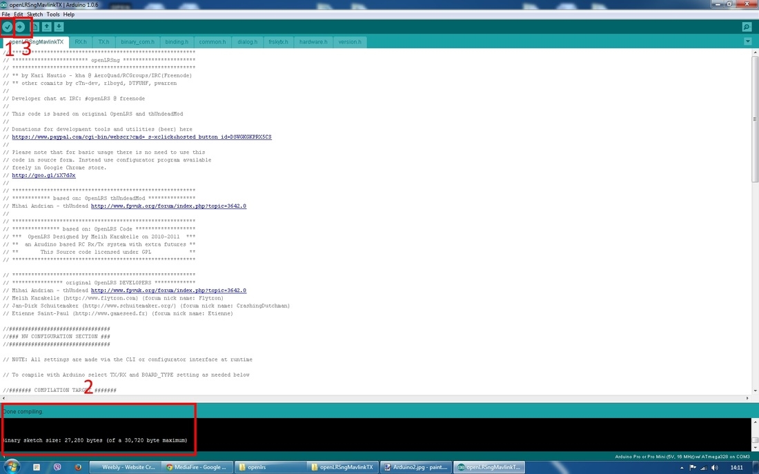
Open openLRSngMavlinkTX folder downloaded from the link above (extract it in your desktop)
Open the file openLRSngMavlinkTX.ino inside the openLRSngMavlinkTX folder (it will open with Arduino IDE)
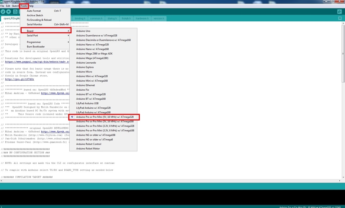
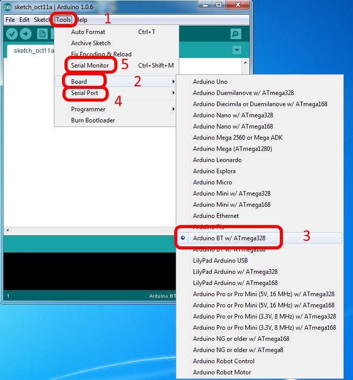
Choose Tools->Board->Arduino Pro or Pro Mini (5V, 16MHz) w/ Atmega328
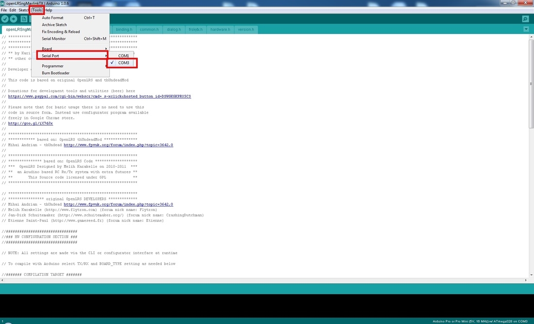
Again choose Tools->Serial Port and choose the port you have your FTDI connected (mine is Port 3 in this case)
On the left upper corner click Verify (the first symbol) and wait for the program to compile the code
After compilation finishes, click Upload (the second symbol with an arrow pointed to the right)
Arduino IDE will compile the code again and then it will start uploading it on the TX
After it finishes uploading the code to the TX, disconnect the FTDI from the TX and connect it to your RX
Be careful when connecting to the RX, match the 3.3V pin
Close Arduino IDE
Now open the file openLRSngMavlinkRX.ino inside the openLRSngMavlinkRX folder
Repeat the above steps
You finished flashing the TX/RX with Openlrsng - Glitsy firmware
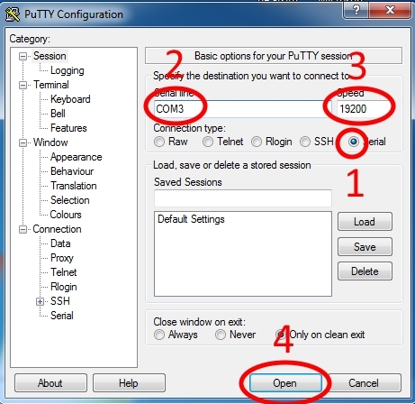
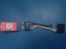
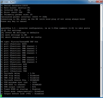
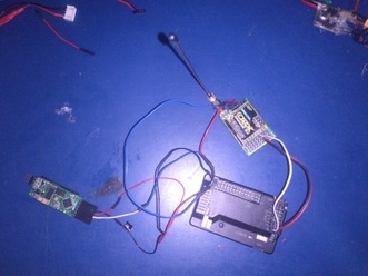
To configure TX/RX modules with Putty, we need to put the TX module in bind mode by connecting it to the PC through FTDI. This means we need to power the module on from the handset battery. In this case, we don't need the 3.3V power supply from the FTDI board, so we have to find a solution to not use it. You can bend the VCC pin on your TX module or better you can make a cable like i did, where the VCC pin is missing like in the picture below. This method is better because while bending the pin, you may damage it or create a short inside. So when you flash the firmware to the TX you put the FTDI directly to the TX module, and when you want to configure the TX/RX with Putty (or any other terminal program) you just use the cable without the 3.3V pin. I suggest you first read the whole procedure before beginning, so let's beginn.
Turn off the Handset
Connect your FTDI through the DIY cable to your TX module and to PC (you do this before opening Putty)
Choose connection type: Serial, select the right port (mine is COM3 as you remember from Arduino), set Speed to : 19200 and click Open Fig. 28
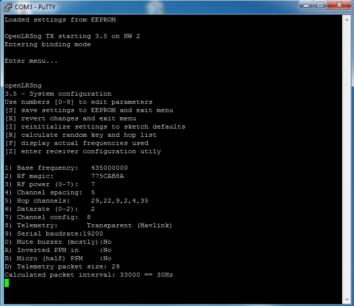
Now, push and hold the OK button on your TX module while turning on the handset. on the screen you will see the message that settings have been loaded (Fig. 30). Don't let go of the OK button until you hear a beep from the TX
After the beep, let go of the OK button, now the TX will start beeping fast and you will see a message that says "Entering binding mode" (Fig. 31)
Click Enter on your keyboard and you will have the options displayed on the screen like in Fig. 32. Settings are already set so you don't need to change anything, but in case you have to, you just type the number or letter you want to change the actual value and follow the instructions there. When you finish, don't forget to type the letter "s" to save the settings.
If you don't get the settings on the screen, start again, you might have missed a step.
Fig. 26 DIY cable without VCC wire
Fig. 27 Connection of TX module to PC through FTDI
Fig. 28
Fig. 29
Fig. 30
Fig. 31
Fig. 32
Now we are going to take a look at receiver settings. We will access receiver settings wirelessly so we must bind the receiver to the transmitter, while the TX is in configuration Menu.
While the TX is connected and you have the TX settings in Putty, supply power to the RX.
Click letter "z" in the keyboard to access receiver settings
Change as needed and don't forget to save with letter "s"
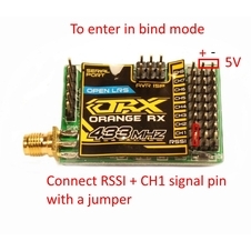
If for some reason you don't get the receiver menu, try to enter bind mode manually. You can do that by using a jumper on port 1 and 2 of the receiver. Connect signal pin of RSSI + CH1 with a jumper.
Connect Port1+Port2 with a jumper (Fig. 33)
Supply 5V power to the rx using an ESC or an external BEC
Click letter "z" in keyboard to access receiver settings
Fig. 34 Receiver settings in Putty
Fig. 33 Manual bind mode
In Fig. 34 you can see my settings. Port 1 is RSSI, port 6 which is channel 5 is PPM. Click "s" to save the settings and remove the RX from power. Do the same with TX and you are finished.
Download Mission Planner Version 1.3.16 here (newer versions don't save sr0 settings on your APM, don't use newer versions or you will lose the settings every time you connect the APM to Mission Planner)
Connect APM to the PC using USB cable and start Mission Planner
(When connecting with USB you must set baudrate to 115200)
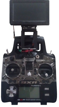
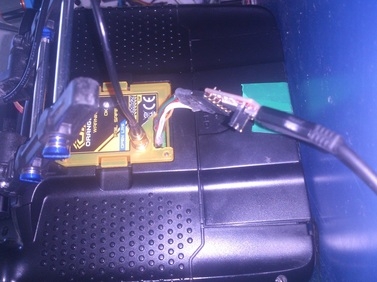
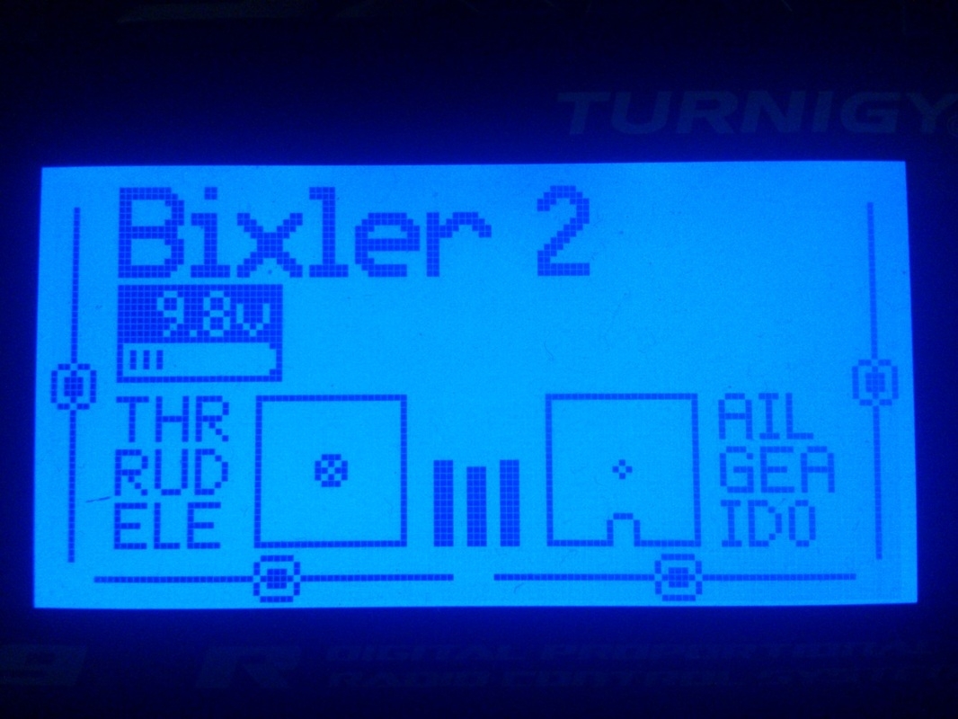
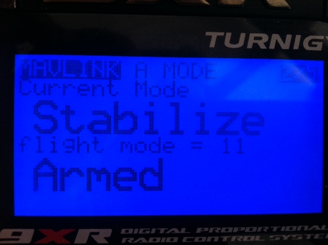
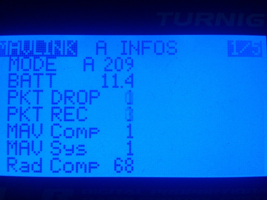
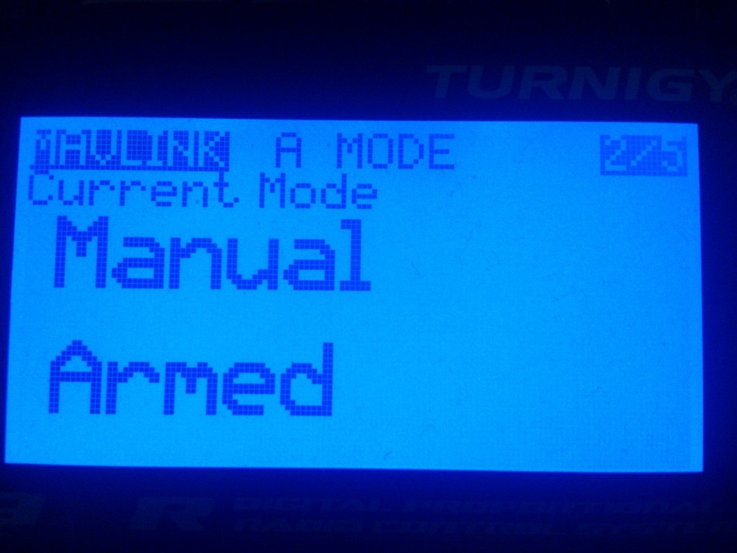
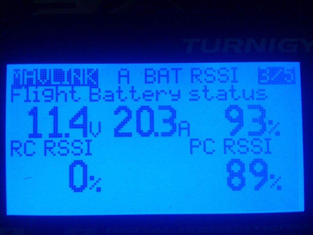
Now that everything is ready, put the TX module on your handset and using the diy cable that we used earlier (Fig. 25), connect the FTDI board to the 9XR and to a USB port on your PC (Fig. 38). Turn on the handset and supply power to your receiver and APM. Open Mission Planner, select the right COM port, set Baudrate to 19200 and click Connect. Mission planner should start loading the parameters from your APM. Push and hold Down button on your handset until you see the telemetry menu with telemetry data showing on your Turnigy 9XR screen. Navigate through different telemetry screens with Up and Down buttons on your handset (Fig. 39).
Fig. 38 TX module connected to PC using FTDI
Fig. 35 Telemetry values in APM
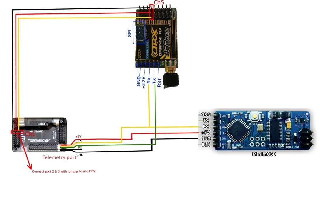
Connect +5V from APM to MinimOSD
Connect TX from APM to RX of MinimOSD
Connect TX from APM to RX of OrangeRx receiver
Connect RX from APM to TX of OrangeRx receiver
Connect GND from APM to MinimOSD
Connect Ch5 of the receiver to Ch1 of APM INPUTS
(don't forget to connect pin 2 and 3 of APM inputs with a jumper)
By default on MinimOSD, telemetry rate is set to 57600, but since we are using 19200 on all our devices, we must change it to 19200 on the MinimOSD as well.
#define TELEMETRY_SPEED 57600 // How fast our MAVLink telemetry is coming to Serial port
#define BOOTTIME 2000 // Time in milliseconds that we show boot loading bar and wait user input
// Objects and Serial definitions
FastSerialPort0(Serial);
OSD osd; //OSD object
//SimpleTimer mavlinkTimer;
Fig. 45 Default MinimOSD Telemetry Speed
As you can see, the telemetry speed is set to 57600, so we need to change it to 19200. I will do the changes for you and share the links of modified files so you don't have to change anything.
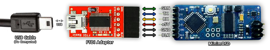
Connect MinimOSD to PC through FTDI Adapter (Fig. 46)
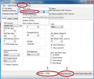
Extract MinimOSD Config Tool somewhere on your PC and open it
Select the right COM port and click Read From OSD
Click Options-> Update Firmware...
Select the firmware you downloaded (Copter or Plane .hex file)
The firmware will start uploading on your MinimOSD. Once done, you can configure your MinimOSD the way you want it. For more info about configuring MinimOSD, burning the bootloader, flashing firmware, modifying and updating charset, take a look at my video below.
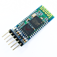
Most of the time, we don't fly at home, but somewhere else in a field, which means, if you want to use a ground station, you can't take your desktop with you. So you would need a laptop and/or a cellphone/tablet. This makes things easier because we can install a Bluetooth module to our Turnigy 9XR handset and connect it to our laptop/cellphone/tablet and there is no need for wires. In this tutorial i will show you how to install a HC-05 Bluetooth module in your 9XR.
Fig. 48 HC-05 Bluetooth module
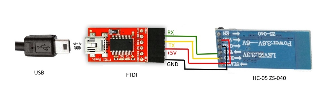
Fig. 49 Bluetooth to PC connection through FTDI
First we are going to setup the Bluetooth module and set Baudrate to 19200.
Connect Bluetooth to PC using FTDI (Fig. 49) led will flash fast
Open Arduino and choose Tools->Board->Arduino BT w/ATmega328
Choose your COM port
Disconnect only VCC wire from the Bluetooth
Push and hold the button on Bluetooth while connecting the VCC wire to get into AT-mode
(If you have another model of Bluetooth with pin KEY instead of EN, you must connect VCC to that pin as well to get into AT-mode), after programming it, you disconnect VCC from KEY pin
Once you get into AT-mode, led will flash slower
Open Serial Monitor (Fig. 51)
On the bottom select "Both NL & CR" and "38400 baud"
In the TextBox type AT and hit Enter or click Send you should get OK
Type AT+VERSION and you should get the version of your BT module
Type AT+NAME=YourName to set a new Bluetooth Name
Type AT+PSWD=YourPassword to set a new password (default is 1234)
Type AT+UART=19200,0,0
Type AT+UART and you should get now 19200
Fig. 51 Setup HC-05 with Serial Monitor of Arduino
Fig. 50 Using Arduino's Serial Monitor to setup HC-05 Bluetooth
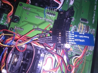
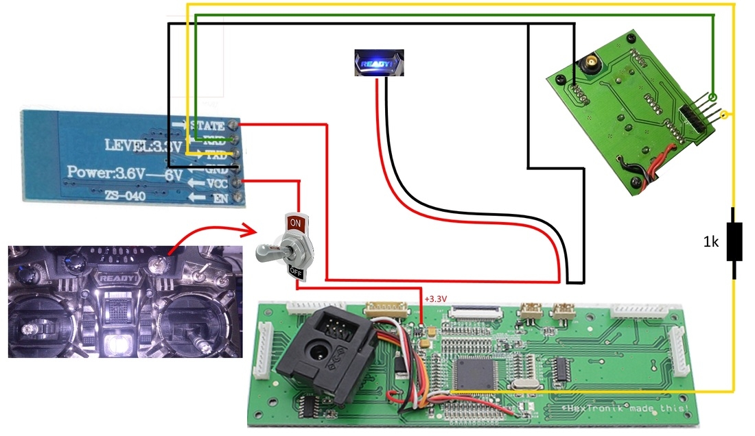
So now that you have configured the BT module, you need to connect it to your 9XR handset. I wanted to use a switch to turn on/off the BT module and since i never really liked the Ready blue light, I wanted to use it as a BT transmit/receive indicator.
Fig. 52 My BT module setup
Fig. 53 shows how i connected everything together. You can use either the 3.3V source like in the picture below, or you can use a 5v to 3.3v voltage regulator.
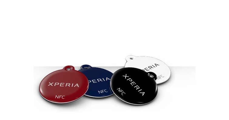
NFC ( Near Field Communication ) tags (Fig. 54) or also called smart tags are smart little chips that'll allow you to snag digital information with your smartphone at short range. This means you program your smartphone to do a specific task or change to specific settings, once approaching a NFC tag. This is a great idea because you setup your phone with a tag once and you can use it in your everyday life just with an approach. For example you can leave a smart tag in your office and program your phone to silence itself, set a reminder, lunch time etc. once touching it. Or you can program a smart tag in your car to open Navigation app once you put the phone in your phone holder etc. This is a great choice for us too because we could stick a smart tag at the phone/tablet clip or on our Turnigy 9XR handle, so it turns on the Bluetooth, opens Tower apk and connects to it once you put the phone/tablet in the phone clip mounted on your Turnigy 9XR radio.
Fig. 54 NFC Tags
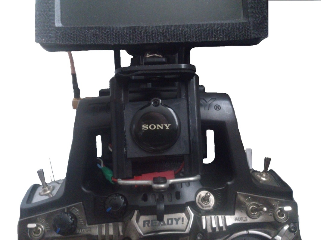
Fig. 55 Turnigy 9XR with FPV monitor and phone clip
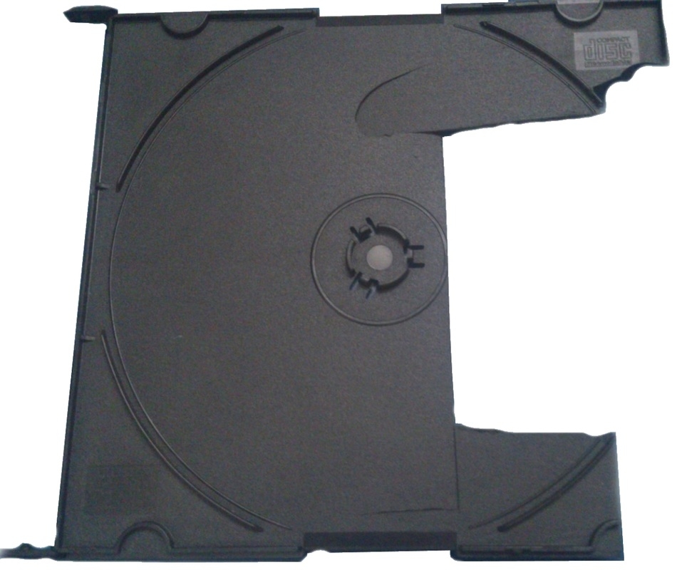
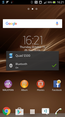
I have a Sony Xperia S smartphone which i use as ground station. So took a plastic CD case and cut a rectangle big enough to fit between the space of the cellphone clip (Fig. 56). I attached the NFC Tag to the piece of plastic with the provided double stick tape (Fig. 57) and glued the piece of plastic to the phone clip with CA glue and Activator (Fig. 58). Once done that, I opened phone settings and activated NFC option. Put the phone on the clip and the wizard started to configure the actions once the phone is near the NFC Tag. So i activated Bluetooth, WiFi, Data Traffic, and open Tower, and also the end actions to turn them all off. Now i turn on the radio, turn on the Bluetooth on the radio with the DIY switch, and put the phone on the clip. The NFC tag activates the services and opens Tower so i just click Connect and done. Very easy and convenient.
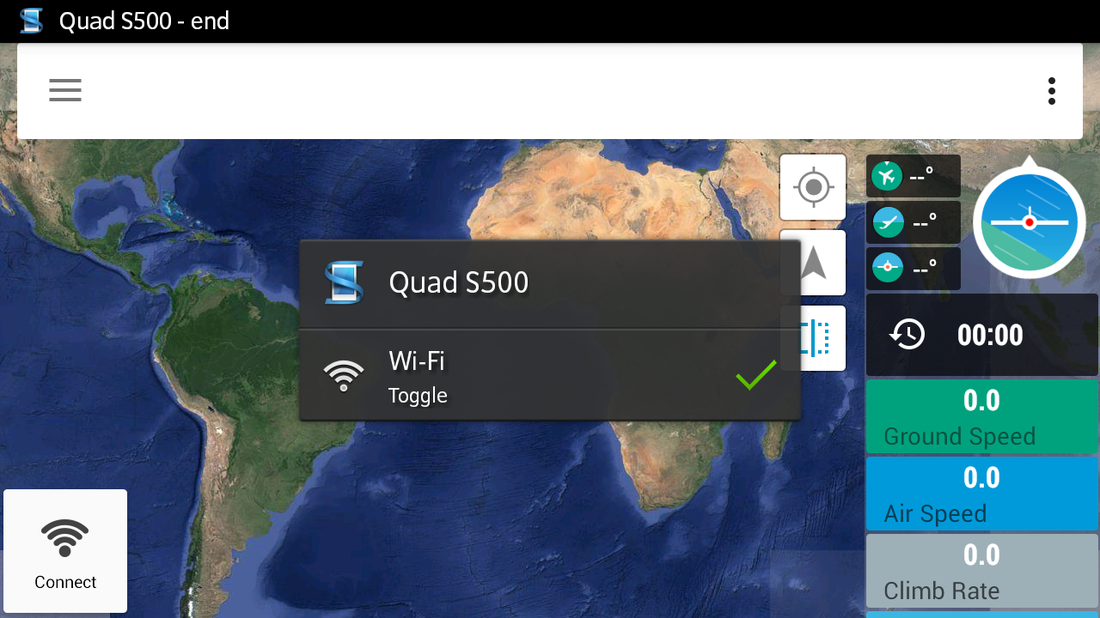
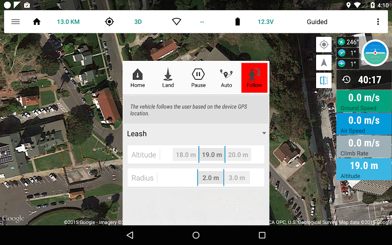
Tower is a great android app that allows you to connect to the APM wirelessly and control it through a phone/tablet. To use the Tower, you need two telemetry radios, one of them connected to the telemetry port on the APM and the other one connected to your phone through an OTG (On The Go) cable or Bluetooth. But since we are already transmitting/receiving mavlink telemetry data with our LRS system, we don't need telemetry radios. We can connect our phone to the handset using Bluetooth. Once you install and setup a Bluetooth module to your 9XR like explained above, and using NFC tags, you will be able to connect to Tower only by placing your phone in your phone clip. Tower as an app is fantastic. You have so many options and info about it all over the web. Check the previous post about connecting to Tower with NFC Tags.
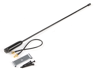
OrangeRx LRS stock antennas are not very good, so you should think about upgrading them to get better ranges. Even though the transmitter is rated at 1W, power alone is not enough. To achieve better ranges, antenna is the key factor. There are people that have stunning ranges with 200 mw transmitters but with good antennas. For the handset, I chose the RMILEC UHF435MHz SRC771 1/2 Wave Length UHF Antenna w/9XR Mount from Hobbyking (Fig. 62). It is a great antenna which comes together with a Turnigy 9XR mount and an extension cable which makes it perfect for the Open LRS Transmitter module.
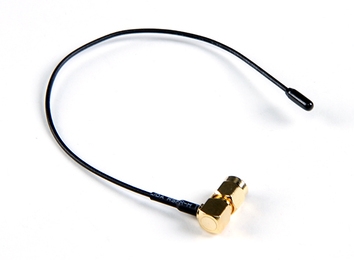
Fig. 63 ImmersionRC 433Mhz "Sander" Antenna
Fig. 62 Rmilec UHF 433Mhz 1/2 Wave Antenna
For the RX, I'm currently using the ImmersionRC 433Mhz "Sander" Antenna from Hobbyking (Fig. 63). It is working great but to be honest I haven't checked the range yet. In the future I'm planning to build a dipole Antenna myself for the Rx. For the moment i'm not getting the desired flight time with my S500 quad, so i'm using FrSky 2.4 Ghz on quad with 5.8 Ghz Video, and Open LRS on Plane with 2.4 Ghz Vido transmission.


Advertising